Injection Machines
6Performance-driven injection molding machines.
Extrusion Machines
3Versatile plastic extrusion systems.
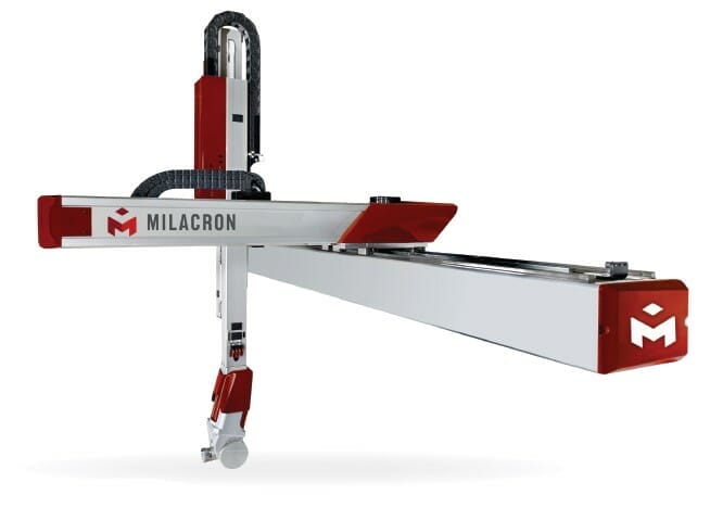
Auxiliary Equipment
6Streamlined automation solutions for every step in plastics manufacturing.
Parts & Service
5Parts, Service, Digital, and Rebuild & Retrofit.
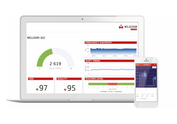
Digital Solutions
1IIOT Platforms that turn data into a competitive advantage.
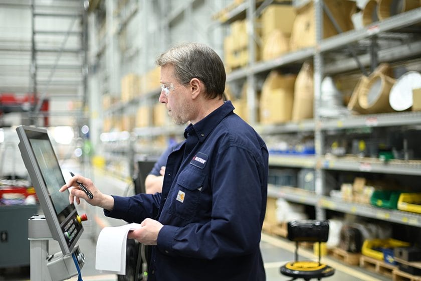
Tech Support
Training and service designed to minimize downtime and improve efficiency.